Mains, but if you’re buying replacement fluorescents then all remains as is (to state the obvious).
To be pedantic, the item you mention is a choke, not a transformer.
Mains, but if you’re buying replacement fluorescents then all remains as is (to state the obvious).
To be pedantic, the item you mention is a choke, not a transformer.
Thanks for that. I have to admit that I have no idea what a choke does. I thought it was a transformer due to the weight of the thing.
So when the packaging of the LED tubes on sale at the Brico states that an appropriate starter is required for the tube to function, basically that isn’t true then.
I am very appreciative that you are willing to share your knowledge about such things. Thank you.
Correct.
I changed the fluorescents in the garage and cave to LED years ago. The thing I wanted most was instant on instead of bizip… bizip… flash, flash, which did my head in.
Electronic starters mostly do that as well (the good ones which pre-heat the filaments do introduce a slight delay though).
Consign them to the history books
I didn’t know that. All my tubes and starters were fifteen years old or so. The change to LEDs was painless. Just new tubes and dummy starters.
I didn’t know about chokes using power, but I’m not sure I’ll have a fiddle to remove them, if it ain’t broke etc. ![]()
The old models with chokes didnt usually have starters, the later ones with ballasts did AFAIK, anyway you dont need either and unbolting is just a pfaf as you often needeed access to the back of the light which was not allways possible if ceiling mounted
For anything new - completely agree. But I wouldn’t change to LEDs for the sake of it. I switched to LED in the garage at home because I wanted brighter for the same power input, conversely the fluorescents n the basement chez moi en France are fine and I’m not in a hurry to change.
It resists or “chokes” AC current. More efficient than a resistor for AC circuits because you don’t get much power dissipated in the choke itself, they also have an interesting property when you quickly interrupt current flow through them.
Traditional fluorescents have a schematic like this
The starter bulb is basically a neon lamp with a bimetalic strip inside. Initially current flows through the inductor(choke) through the lamp filaments and through the neon, which heats up the bimetallic strip. After a second or so the contacts close and the neon starts to cool as it is shorted out by the switch contacts. This means that after another second or so the contacts will re-open. This cycling open and closed of the contacts would continue if nothing else happened - in fact if the lamp does not strike it will continue which is what we see when the tube gets old and doesn’t strike properly.
Initially not that much current flows - really just enough for the neon, but once the contacts close current through the inductor (choke) increases. It is passing through the filaments so it they heat up (they need to be hot to emit electrons for the arc)
An inductor(choke) is just a coil of wire - with current flowing we now have an alternating magnetic field created around the coil. When the bimetalic strip in the starter opens the contacts, current stops flowing - which means the magnetic field rapidly collapses. Anyone who remembers basic physics knows that a coil of wire in a changing magnetic field will generate a voltage (it’s how a dynamo or generator works). This is higher than the mains voltage and strikes an arc along the length of the tube - the arc current flows from the inductor, through the tube and the mains wiring. Probably through C2 as well but that’s not its main role. The arc ionises the gas in the tube and current flows through it.
Now the voltage across the tube drops, the choke regulates overall current flow to avoid damage to the tube. The voltage across the starter is also too low to light the neon so it drops out of the picture.
C2 helps power factor correction and I’m pretty sure C1 is just there to reduce arcing of the contacts in the starter otherwise they would burn out even more quickly than they do.
More explanation & physics here, plus some stuff on electronic starters.
Just check the actual power consumption of the light fitting compared to watt the tube states (intended miss spell) it could be double or a bit more as I discovered so a reason to change possibly.
Yes, fluorescent lighting systems have losses which increase overall power consumption - but that is true of everything electronic/electrical.
Cheap LED systems sometimes have terrible power factors - and if suppliers start charging for apparent power rather than real power you’ll be in the same boat.
Just not by the same magitude that I have tested. Generally more lumens per watt as well and in many cases all the light is downward rather than fluories which are more 360 degrees which is sometimes what you want but not always.
Just as with LEDs, reflectors are available.
Thank you for an intelligent and insightful explanation.
My experience is that the stated tube wattage is pretty much the same as the total actual consumption.
I have a 4 foot, 36 watt, tube fitting on the end of a length of cable which I use as a work light. By plugging it into a socket adjacent to the Linky meter, at a time when overall consumption is low and stable, it appears to consume 38 watts. Pretty close to the 36 marked on the tube.
Of course the Linky could always be wrong perhaps.
Thats fine Robert, having checked a large number of old installations of tubes and 28w 2D bulkheads they were consuming double the power. These were old fittings with large chokes, later stuff with electronic ballasts were far better.
That’s because you were measuring apparent power rather than real power. Domestic meters measure real power, whereas industry is charged for apparent power, which makes power factor correction a necessary thing.
Depends on the power factor, of course. Not sure what the average is for fluorescent but the article I linked discusses this and suggests that the PF for the worked example was 0.97 - not enough to explain Corona’s observations.
There *are* losses though - inductive “chokes” heat up, as do the filaments of the lamps themselves (though I suppose that latter loss should be included in the lamp power rating).
My Linky gives me consumption in VA, not kW - I’m sure the suppliers would love to charge domestic users for apparent power as electronic devices (especially LED lumieres) often have poor power factors - eg my UPS tells me that the server, connected monitor and network switches between them have a PF of about 0.88 - I’m sure my supplier would be more than happy to charge 12% extra for this ![]()
APC : 001,046,1160
DATE : 2025-01-27 09:39:19 +0000
HOSTNAME : ***
VERSION : 3.14.14 (31 May 2016) redhat
UPSNAME : APC UPS
CABLE : Custom Cable Smart
DRIVER : MODBUS UPS Driver
UPSMODE : Stand Alone
STARTTIME: 2024-10-24 15:52:25 +0100
MODEL : Smart-UPS 1500
STATUS : ONLINE
LINEV : 239.4 Volts
LOADPCT : 12.0 Percent
LOADPWR : 119.8 Watts
LOADAPNT : 9.0 Percent
APNTPWR : 135.1 VA
BCHARGE : 100.0 Percent
TIMELEFT : 36.0 Minutes
MBATTCHG : 5 Percent
MINTIMEL : 3 Minutes
MAXTIME : 0 Seconds
OUTPUTV : 239.4 Volts
DWAKE : 0 Seconds
DSHUTD : 0 Seconds
LOTRANS : 207.0 Volts
HITRANS : 253.0 Volts
ITEMP : 31.1 C
BATTV : 26.2 Volts
LINEFREQ : 50.5 Hz
OUTCURNT : 0.53 Amps
LASTXFER : Automatic or explicit self test
NUMXFERS : 8
XONBATT : 2025-01-23 20:25:18 +0000
TONBATT : 0 Seconds
CUMONBATT: 76 Seconds
XOFFBATT : 2025-01-23 20:25:28 +0000
LASTSTEST: 2025-01-23 20:25:21 +0000
SELFTEST : OK
STATFLAG : 0x05000008
MANDATE : 2020-10-15
SERIALNO : AS****
BATTDATE : 2021-01-13
NOMOUTV : 230 Volts
NOMPOWER : 1000 Watts
NOMAPNT : 1500 VA
FIRMWARE : UPS 04.1 / 00.5
END APC : 2025-01-27 09:39:39 +0000
I need a bit of help if possible?
I have been meaning to change my garage lights for a while now as they are a bit dim. I had no idea LED replacements were available until I read this thread so I ordered a couple to preplace the pair I already have.
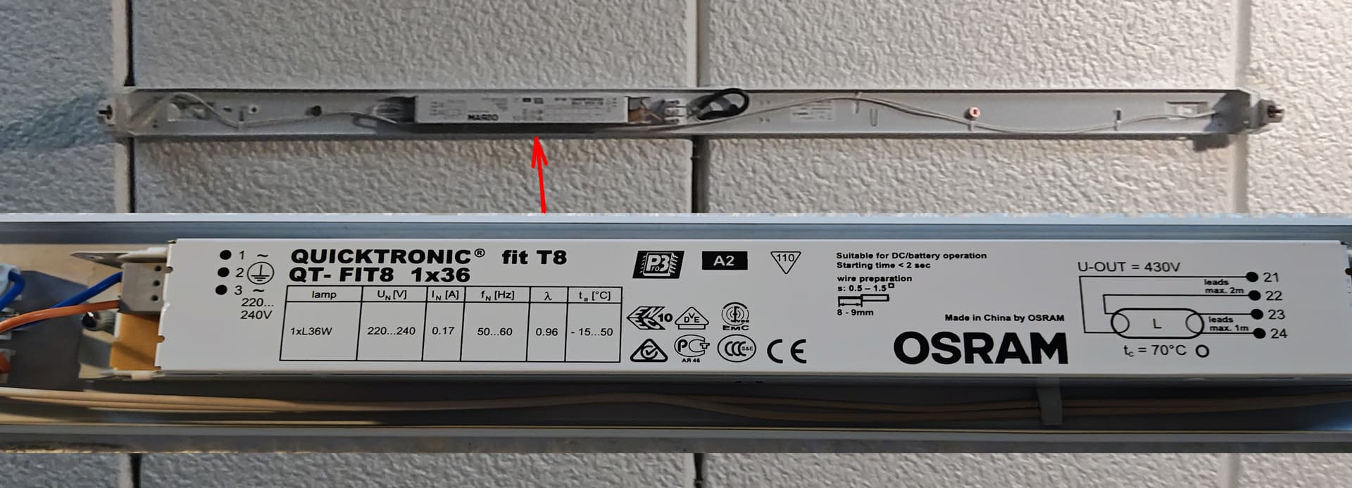
The instructions say replace the Tube Starter with the LED tube starter supplied with the new LED lights. When I opened my existing fluorescent light covers, I cannot see a starter. Do I just replace the old light with the new one and that’s it or is something else required? Also does it matter which end goes where?
That is because you have a more modern unit, with an electronic ballast. You can get LED replacements specifically for retro fitting to such a unit.
However, looking at the wiring in your picture it would be a very simple process to disconnect the internal gubbins from the incoming connector block, cut the two wires running to the right hand end (in the full view/top picture) & connect them directly into the block. That will create a live & neutral arriving at the lampholder at one end of the fitting. As long as you put the correct end (which will be marked) of the new LED tube into that, it will work.
This is a lot less work than putting up a new fitting.